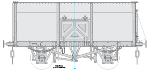
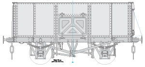
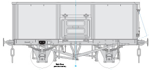
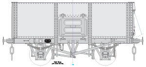
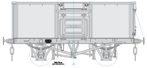
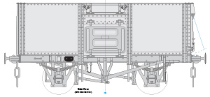
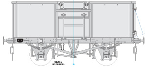
Steel Mineral Railway Wagons
MoT Post-War Production
Scale Drawings for Models
This page describes the scale drawings I have available for you to produce models of all-metal railway wagons that were used to carry minerals such as coal for the commercial customers of the railway companies. Most of the wagons on this page were ordered by the Ministry of Transport after World War II. Many weren't delivered until after nationalisation. Similar wagons for other periods are covered by separate pages. This page covers those wagons with the traditional rectangular body shape, similar wagons with wooden bodies, and hopper wagons, will also be covered by separate pages.

Diagram 1/100 wagon,
MoT livery.
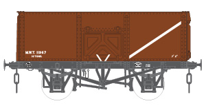
Diagram 1/101 wagon,
MoT livery.
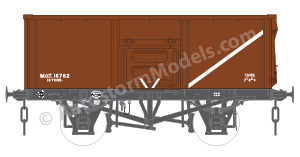
Diagram 1/102 wagon,
MoT livery.
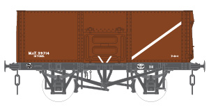
Diagram 1/103 wagon,
MoT livery.
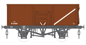
Diagram 1/102 wagon,
hybrid MoT/BR livery.

Diagram 1/100 wagon,
British Railways livery.
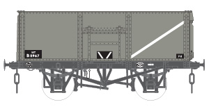
Diagram 1/101 wagon,
British Railways livery.
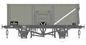
Diagram 1/102 wagon,
British Railways livery.
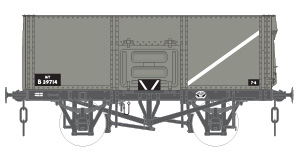
Diagram 1/103 wagon,
British Railways livery.
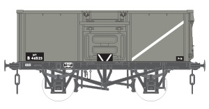
Diagram 1/104 wagon,
British Railways livery.
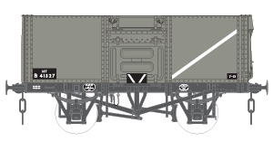
Diagram 1/105 wagon,
British Railways livery.
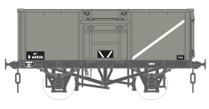
Diagram 1/106 wagon,
British Railways livery.
Note: Clicking on any of the images on this page, such as those above, will cause a larger version of the image to appear in a new tab or window of your browser (depending on how your browser is set up).
The Drawings
As with all of my standard drawings, each drawing is available in a range of scales, from 2mm:1ft (N gauge) to 16mm:1ft, and most common scales in between. Once you have bought a particular drawing, you will be able to download versions of it in any or all of the available scales. At extra cost I can also provide copies of drawings at a specific scale printed onto A3 or A4 paper and sent to you by post.
The drawings will be provided as multi-page PDF files, one file for each scale. The first page in the file contains the full drawing, arranged for on-screen viewing. The remaining pages each contain a portion of the full drawing formatted for printing out on A4 or A3 paper. A drawing will consist of a number of views each showing an aspect of the wagon, such as a side, end or plan view. Where a view at a particular scale is too large to fit on A4 paper, overlapping pages are provided for you to join together after printing. Alternative pages are also provided for printing onto A3 paper.
To help with this, alignment guides are provided. These take the form of simple fine-lined crosses positioned on either side of the drawing view where I suggest a join be made – typically at a position where a minimum of fine drawing detail crossed the joint. Select one of the overlapping pages and cut it through the drawing along the guides. Carefully position the cut edge on top of the other page such that the crosses are reformed acros the joint. When you're happy with the alignment, tack the pages together with small pieces of transparent sticky tape (e.g. in the vicinity of the guides). Then use a long piece of sticky tape along the whole joint to properly join the pages together. Turn the joined pages over and add a further length of tape on the back.
For the drawings in the smaller scales (4mm and smaller), I've imposed a minimum line width (of around 0.1mm) so that the drawing remains printable. This unfortunately means that fine details amy become obscured or illegible. I suggest that you use a larger scale drawing to examine the details, and use a drawing at the scale you're working to easily transfer dimensions, or even cut up to use as templates.
The drawings for the wagons listed on this page typically contain a side view (both sides are assumed to be identical, apart from being mirror images because of the single end door), a view of each end, longitudinal and transverse cross-section views to show the interior of the wagon, and plan views of the wagon from above, as a cross-section around half-way down the body, and a plan view of the underframe on its own. Where there are major variations for a design, such as using welded or riveted construction for the underframe, two complete sets of views are provided. More minor variations, such as pressed or fabricated doors, are documented by appropriate partial views. There are also often partial views of specific details that are obscured by other features in the standard views.
As well as these views showing the construction of the wagon, I also provide drawings of the wagon in each of the major livery styles it received during its lifetime. The illustrations on the right are a selection of these livery drawings, reduced in size for on-screen viewing. The illustrations below, alongside side each available wagon type, are also selected views from the corresponding drawings, again reduced in size for on-screen viewing.
To produce these drawings, where possible I've started with an official general arrangement (GA) drawing, if not of the wagon type being drawn, then of a very similar type. From there I incorporate details from other drawings and photographs to produce a fully detailed drawing. Source drawings are often distorted or illegible in places, so unfortunately I can't claim 100% accuracy for my drawings. They should however be very close, and models built to them should look the part and require detailed examination and expert knowledge to detect any errors. A brief description of its origins are included on each drawing, so you can assess the likely accuracy for yourself.
How To Order
A single drawing costs £7.50. Additional drawings ordered at the same time cost £5.00 each. Ordering all drawings on this page as a group will cost £20.00.
Click on the buttons below to add the drawings you want to purchase to your basket. Once you have completed your payment, be sure to return to this site to receive a set of access codes for your purchases – one for each drawing and/or one for the group. These will also be sent to you by e-mail.
Enter these codes on the drawings download page here to be presented with links that you can use to view the drawing files you have purchased, and/or download them to your computer. To make downloading drawings for several scales easier, a combined "ZIP" file is also provided that contains all of the scale files for a particular drawing. Most file viewing apps (Explorer on Windows, or Finder on Mac) provide facilities for unpacking the ZIP file to access the individual files.
To order copies of these drawings printed onto paper, please first purchase the downloadable versions, as above. Then please contact me to request a quote for the printed versions, specifiying which scale(s) you want printed, and whether on A4 or A3 paper. The basic price is £1.00 per sheet of A4, or £1.50 per sheet of A3, plus postage which will also depend on the number and size of sheets required. For these drawings, the smaller scales can be fully printed on a single sheet of A4, while the largest scales can need over 20 sheets. A few sheets of A4 can be folded to fit in a C5 envelope to qualify for the normal letter postage rate. Many sheets of A4 are likely to make a C5 envelope too thick for this and require the large letter rate, so may as well be sent unfolded in a C4 envelope. A3 sheets will always be folded to fit either a C4 or C5 envelope. If you need only a few sheets of A4 and would prefer them to be sent unfolded, please specify this when you request the quote.
Copyright
My drawings are subject to copyright, and are licensed for your personal use only. You are not permitted to modify the files in any way, nor supply copies of them to anyone else, other than to get them printed by a third party. The only exception to this is where you are buying the drawings for a small group of modellers (such as a model railway club) working on a single project.
History
For the first few years after World War II the now Ministry of Transport (formerly Ministry of War Transport) remained in control of railway operations, including the production of new wagons. During this period the MoT ordered many steel mineral wagons. Initially these continued with the wartime Charles Roberts and Hurst Nelson designs, followed by new standard designs that were very similar to the LMS diagram D2109, with either welded or riveted bodies.
Coal traders in the London area had an agreement with the trade unions that limited the height of wagon sides that their workers had to unload. The new MoT wagons exceeded this height limit, so extra top flap doors above the side doors were added to the designs for further new production, including the LMS wagons to diagram D2143. Existing wagons were not modified.
Once the railways were nationalised in 1948, British Railways took over control of the railways, and ownership of the pooled wagon fleet, from the MoT. Many of the post-war wagons ordered by the MoT weren't actually delivered until after nationalisation.
Most, if not all, of these wagons, of all 6 designs, were fitted with pressed steel side and end doors from new. These subsequently proved to be vulnerable to damage, and were later replaced with fabricated versions, of either welded or riveted construction (irrespective of the basic body construction type). Doors were often not all replaced at the same time, resulting in a mix of door types on a single wagon.
There was also a batch of wagons built to a new diagram, 1/106, by BR Derby, just after they completed the D2134 wagons. It is not clear how these wagons differed from the standard 1/104 design. They were built with fabricated doors from new, so maybe that was the justification for the new diagram number. Or they may have copied the LMS D2134 design, which is very similar, but not identical, to diagram 1/104, also with fabricated rather than pressed doors. For the 1/106 drawing listed below, I've assumed a 1/104 design with fabricated doors.
All of these wagons were fitted with bottom doors, so were also fitted with independent dual 4-shoe brakes. That is, each brake lever only operated the brake shoes on its side of the wagon. There was no connecting bar or other mechanism to link operation of the brakes on both sides, because this would foul the opening of the bottom doors.
A large number of the wagons ordered by the MWT to both Charles Roberts and Hurst Nelson designs, were shipped across to France after VE-Day, to help re-establish operations of the heavily damaged French railways. These were accompanied by a large batch of wagons built by Metropolitan Cammell to a much more Continental design, possibly ordered by the Free French Government. Ultimately these wagons proved to be too small for the French, and were returned to British Railways in the early 50s.
The Charles Roberts and Hurst Nelson designs were later given British Railways diagrams 1/100 and 1/101, respectively. The D2109-like designs were given diagrams 1/102 and 1/103, for the welded and riveted versions respectively. The later versions with top flap doors were likewise given diagrams 1/104 and 1/105. The Charles Roberts wagons returned from France were given the standard 1/100 diagram number, but the Hurst Nelson wagons were given diagram 1/113. The wagons of French design were given diagram 1/112.
Most, if not all, of these wagons were finished in a standard MoT bauxite (red-brown) livery, the colour reputedly being the same as the then current LMS shade of bauxite. This included wagons delivered after nationalisation. The very last of these wagons may have been delivered in the new standard BR grey, but this is uncertain. When subsequently repainted, all of these wagons received the then standard shade of grey.
Those wagons delivered before nationalisation were registered as private owner wagons with the various grouping railway companies. Those delivered after nationalisation were regarded as BR-owned. Later wagons received the standard "B" prefix for BR-built wagons to their MoT fleet numbers from new, the remainder received this prefix on subsequent repainting, while keeping their original MoT numbers. All of the markings on these later wagons used the new standard BR Gill Sans lettering and layout, resulting in a hybrid livery of standard BR markings on bauxite. Brief details of fleet numbers are included in each drawing.
Wagon Types
Charles Roberts design, BR diagram 1/100
14/16T, slope-sided riveted body, pressed side doors, fabricated end door, some with bottom doors.
Produced 1939–47, by numerous manufacturers. Some shipped to France, and returned to BR 1950–2.
Hurst Nelson design, BR diagram 1/101 and 1/113
14/16T, rectangular riveted body, pressed side doors, fabricated end door, some with bottom doors. Wagons built for the MoT did not have the intermediate side stanchions.
Produced 1943–5, by Hurst Nelson. Some shipped to France, and returned to BR 1950–2 as diagram 1/113.
MoT Early design, BR diagram 1/102
16T, rectangular welded body, pressed side and end doors, with bottom doors.
Produced 1946–8, by numerous manufacturers.
MoT Early design, BR diagram 1/103
16T, rectangular riveted body, pressed side and end doors, with bottom doors.
Produced 1946–8, by numerous manufacturers.
MoT Later design, BR diagram 1/104
16T, rectangular welded body, pressed side and end doors, with bottom doors and top flap side doors.
Produced 1948–50, by numerous manufacturers.
MoT Later design, BR diagram 1/105
16T, rectangular riveted body, pressed side and end doors, with bottom doors.
Produced 1948–9, by numerous manufacturers.
BR design, BR diagram 1/106
16T, rectangular welded body, fabricated side and end doors, with bottom doors and top flap side doors.
Produced 1950–1, by BR Derby.
All Drawings Group
To add all of the above drawings (including those not yet available, and any added later) to your basket as a group, at a discounted price of £18:
Clicking on an image above will open a larger view in a separate browser window/tab.
Clicking on the "Add To Basket" buttons will add that set of drawings to your basket.

